Input and Output Impedance. Why is this so important?
If you are familiar with the BJT amplifier circuits, I am sure you heard the terms: “input impedance” , “output impedance”. But why do we even care? Lets take a look. But before I show you the circuits, I want to make things a bit clearer. Lets assume we are designing a common-emitter amplifier to boost the weak input voltage that can be coming from a sensor. The modern IC sensors usually have low output impedance. And when you take this signal from the sensor’s output to the input of your amplifier, it forms a voltage divider between the two. Therefore, if your amplifier has a low input impedance, you waste a lot of power and get a low voltage at the input of your amplifier, and that is something that you dont want.
The voltage divider formula is as follows: Vout = Vsource * (R2/R1+R2). And if you do the calculations you may see that if R2 closer or smaller than R1, your Vout will be a fraction of Vsource. Take a look at the Simulation in I setup in LTspice.
First Case (R2 is smaller or equal to R1)
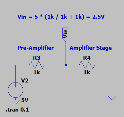
As you can see, of R2=R1=1K, you get 2.5V at the input of the amplifier stage. You basically waste energy for no reason.
Second Case (R2 is significantly larger than R1)
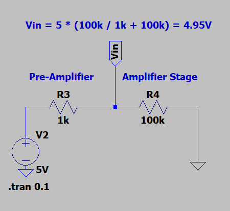
In this case, you get a voltage very close to the Source voltage which is visible in the schematic. You get 4.95V at the input of the amplifier stage.
Therefore, one must pay attention to the input and output impedances of the circuits. If the signal source has a low output impedance, the amplifier should have a high input impedance.