Decoupling Capacitors
If you have designed pcb’s before, I am sure you have seen connecting ceramic capacitors to power terminal of microcontrollers. In this article, I will explain the purpose behind it.
We use decoupling capacitors to provide current almost intaneously to the part in the microcontroller where it is required. Current must be delivered in nanoseconds, but this cant be done by the power supply, because the wiring that connects power supply to the power terminal of the microcontroller has some inductance, and that resists to the sudden changes of current. This is where capacitors come into play, we connect it as close as possible to the power terminal of a microcontroller, and the current is delivered almost instantenously.
Lets look at two examples, one where we dont have a decoupling capacitor, and one we have a decoupling capacitor.
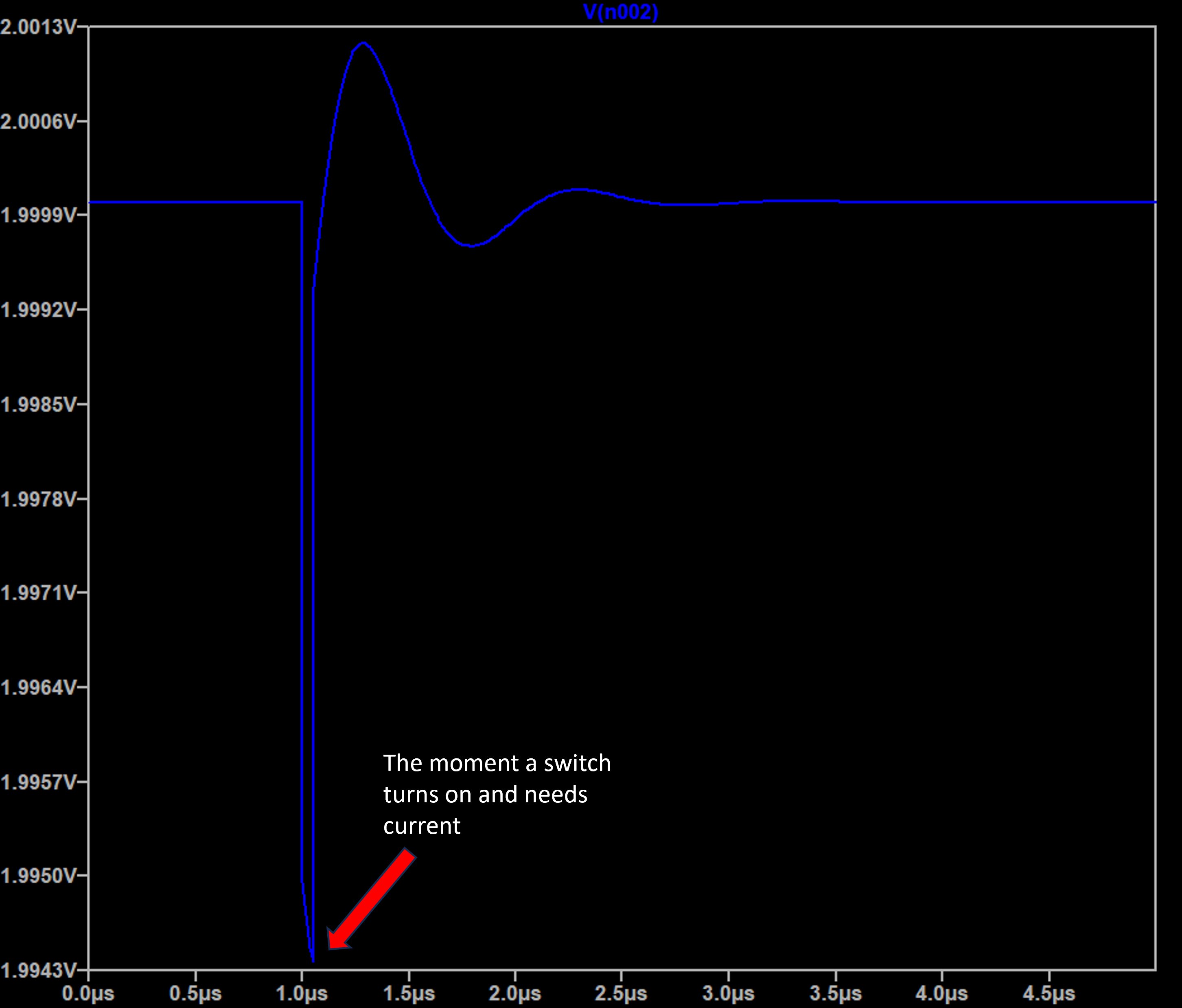
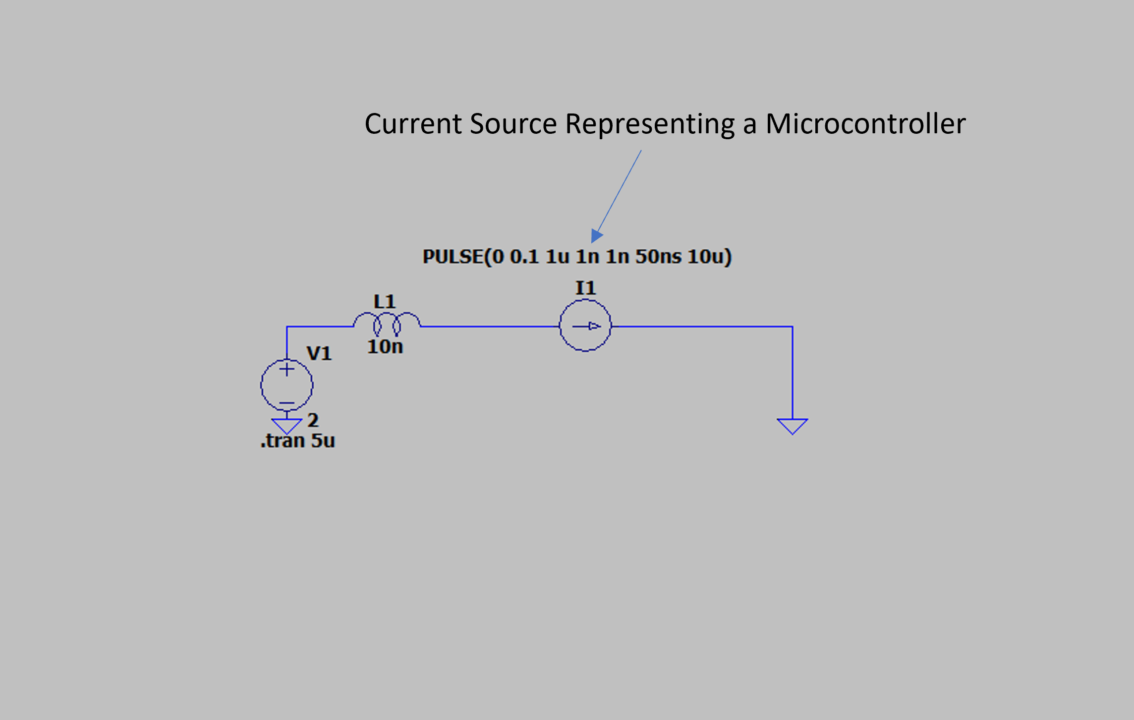
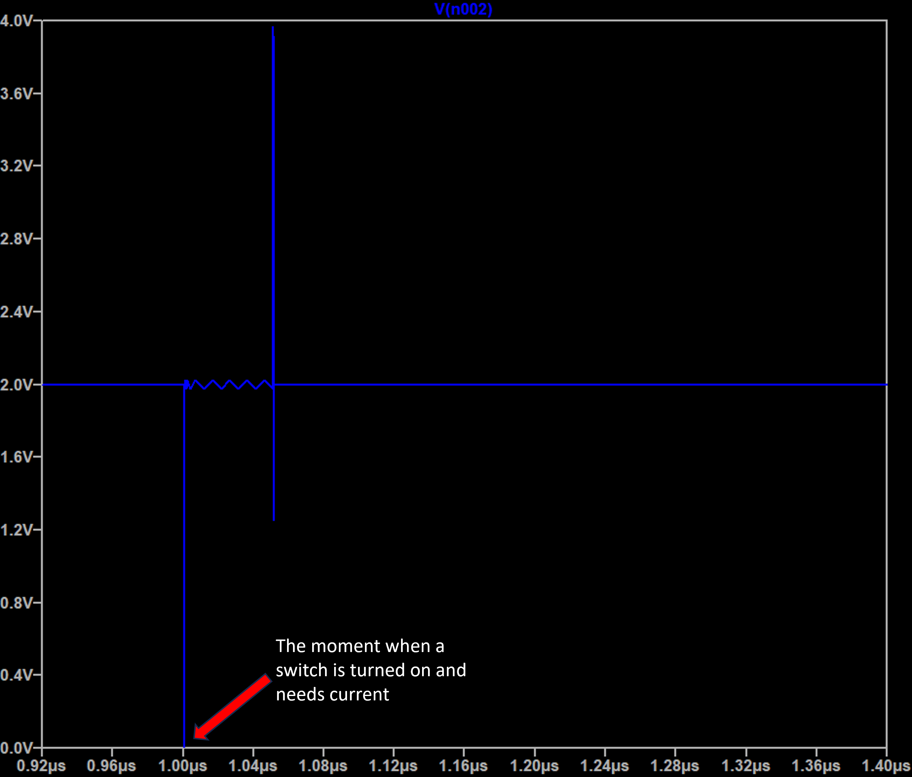
Without a Decoupling Capacitor:
We connect power supply to our microcontroller, represented by a current source that requires 100mA when its turned on. The power line connecting the supply to the circuit has some inductance at nH level. Even if it seems small, it effects the circuits function significantly. See the schematic and the simulation results. The voltage at the pin of the current source oscillates a lot before it can stabilize at 2V, and it takes microseconds to stabilize, which is huge for a 100 Mhz microcontroller. This is caused by the inductance of the wiring, it resits sudden current changes. The power source wont be able to supply enough current in time, therefore microcontroller will malfunction.
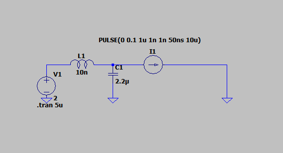
With a Decoupling Capacitor:
Only difference now is we connect a capacitor between the power supply and the ground, differences are huge. When a sudden current is needed, capacitor can supply this current almost instanteosuly for a short amount of time until the power supply can start delivering current at required speed. See the differences in the simulation results, oscillations at the microcontroller terminal is almost non-existent.