Generating PWM Signals With STM32 Microcontrollers
Generating PWM signals with STM32 microcontrollers is straightforward. Just follow the instructions below:
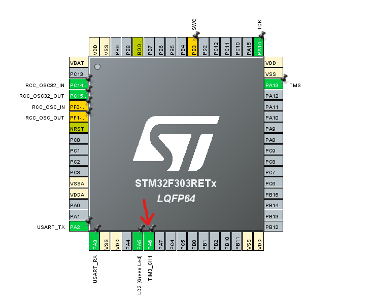
Select an appropriate GPIO pin:
I chose the GPIO pin PA6 and set it to TIM_CH1, meaning Timer 3 and channel 1.
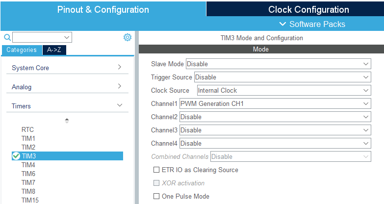
Activate the timer channel and configure settings:
After activating the timer channel you set the pin to, configure the timer source to “Internal Clock” (Unless you want to use an external clock.) then set the Channel1 to “PWM Generation CH1”
Set Timer Parameters:
Use the following formula to get your desired PWM frequency :
- Your clock frequency / ( (prescaler + 1) x (ARR + 1) )
- Duty cycle is: (Pulse / ARR) x 100
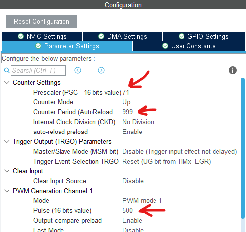
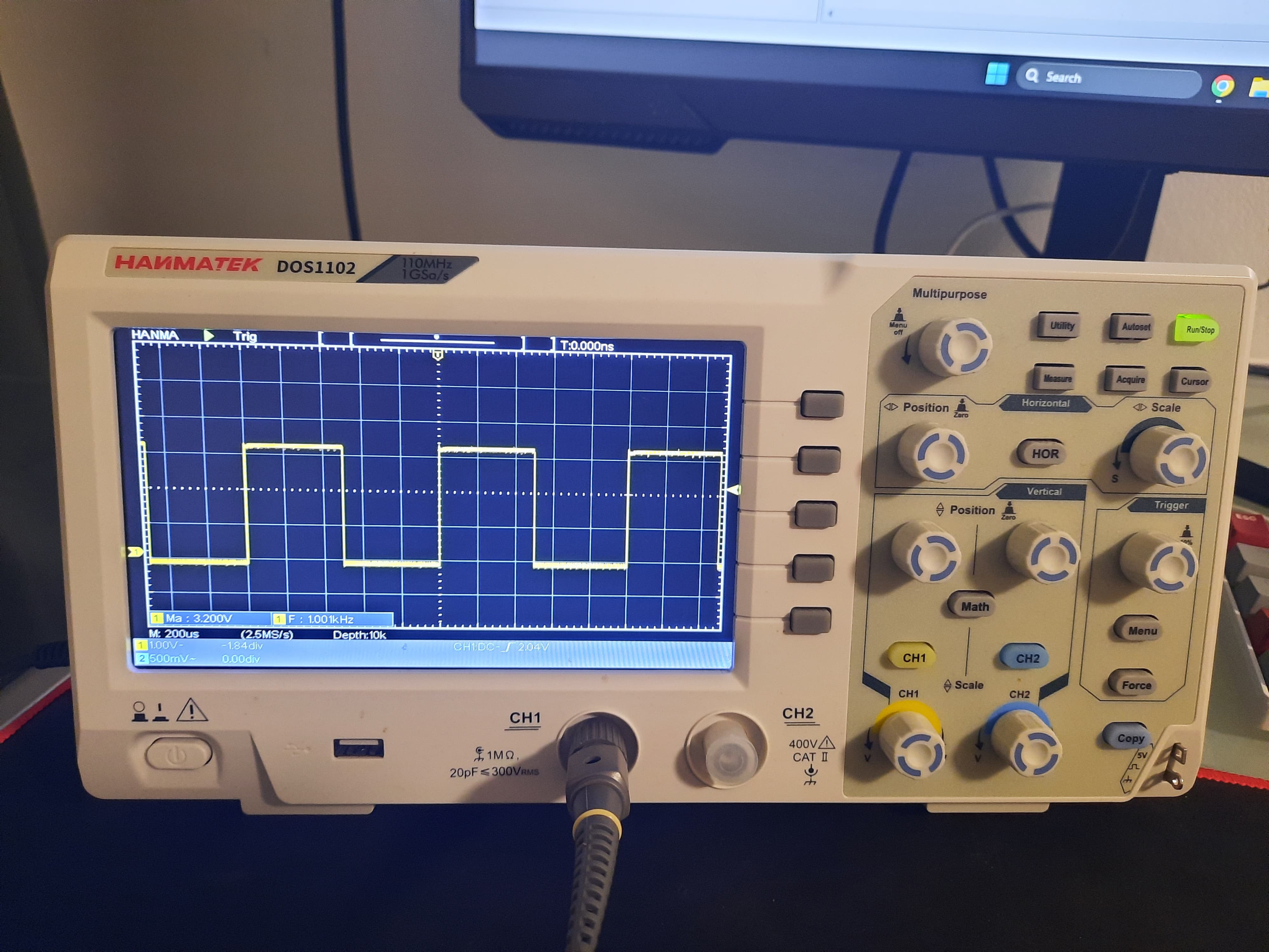
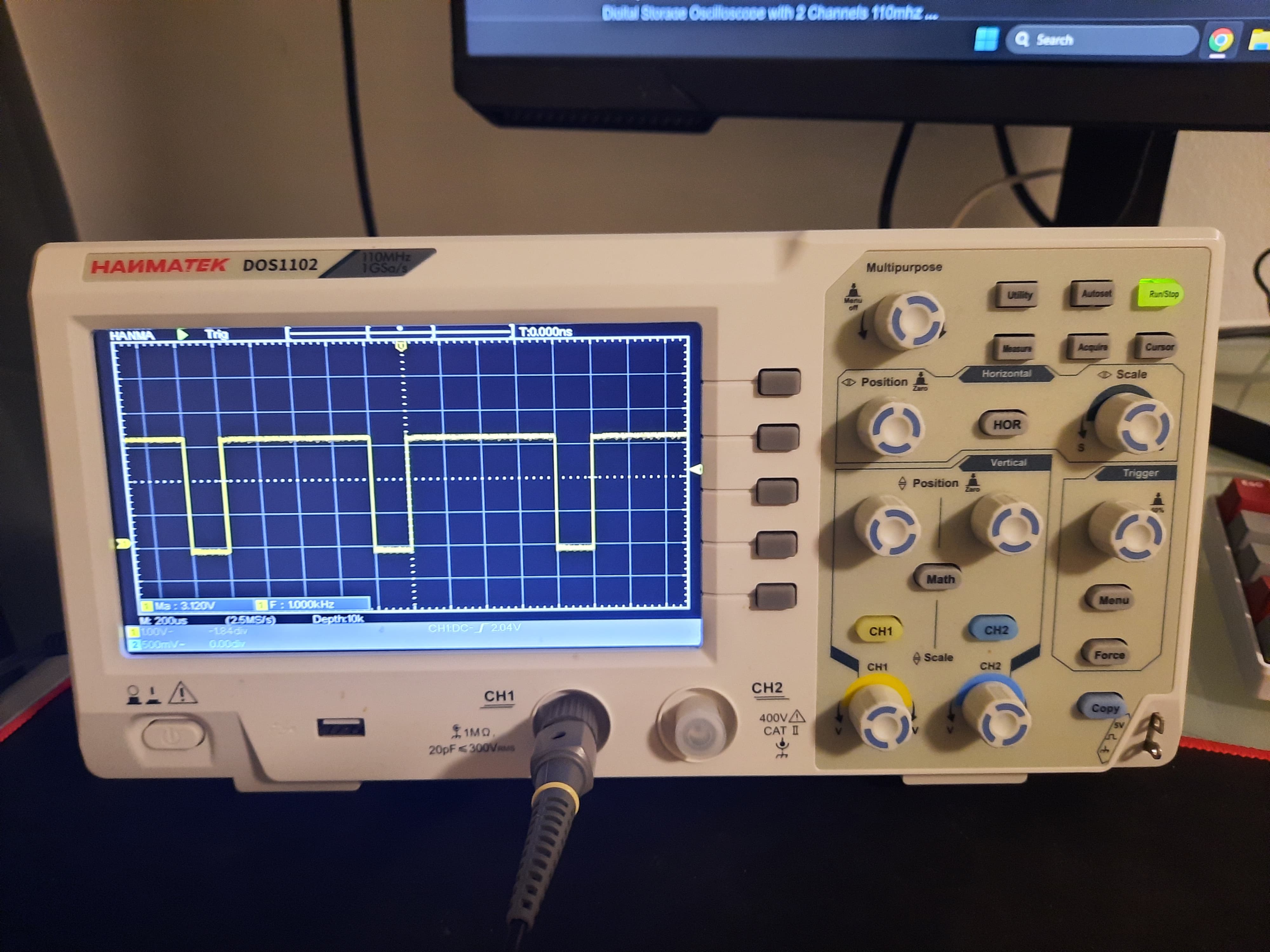
Example:
My clock source is running at 72MHz, I set the values so I get 80 percent and 50 percent duty cycles. These are the results on my oscilloscope: