433 Mhz Bandpass Filter
In the laboratory of my University, I was building a project where I needed to capture 433Mhz signals and measure the amplitude of the signals, But there was a small problem, the antenna that I was using, was picking up significant noise in the 1.3GHz range, which were affecting the overall amplitude of the received signal.
How to solve this? Of course with a bandpass filter!
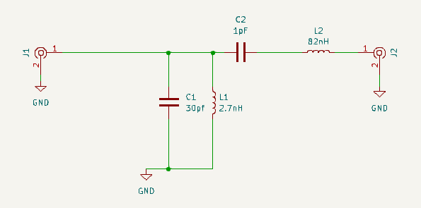
I designed the circuit using inductors and capacitors, created the schematic and also desinged the PCB as below:
The Schematic:
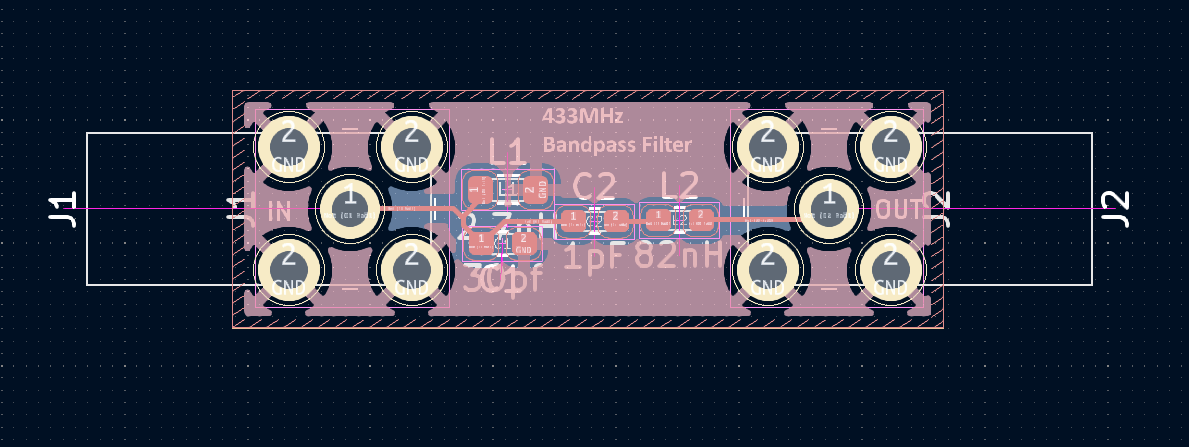
The PCB Design:
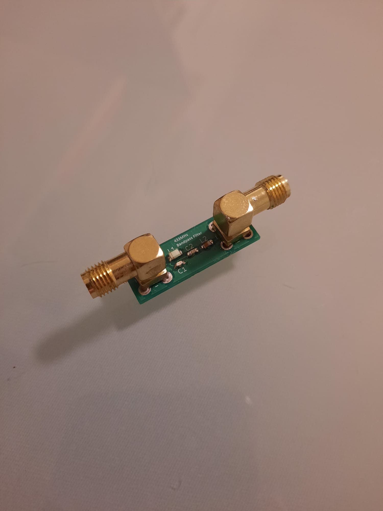
Even though soldering these incredibly small smd parts were too difficult, I have managed to solder them properly.
The pcb looks like this now with sma connectors on both ends:
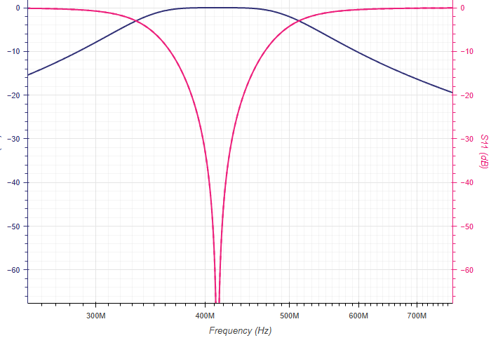
The S parameter shows that the filter is working as intended, having the lowest S11 point at around 400-450 Hz which is exactly what I needed.
The S parameter Test:
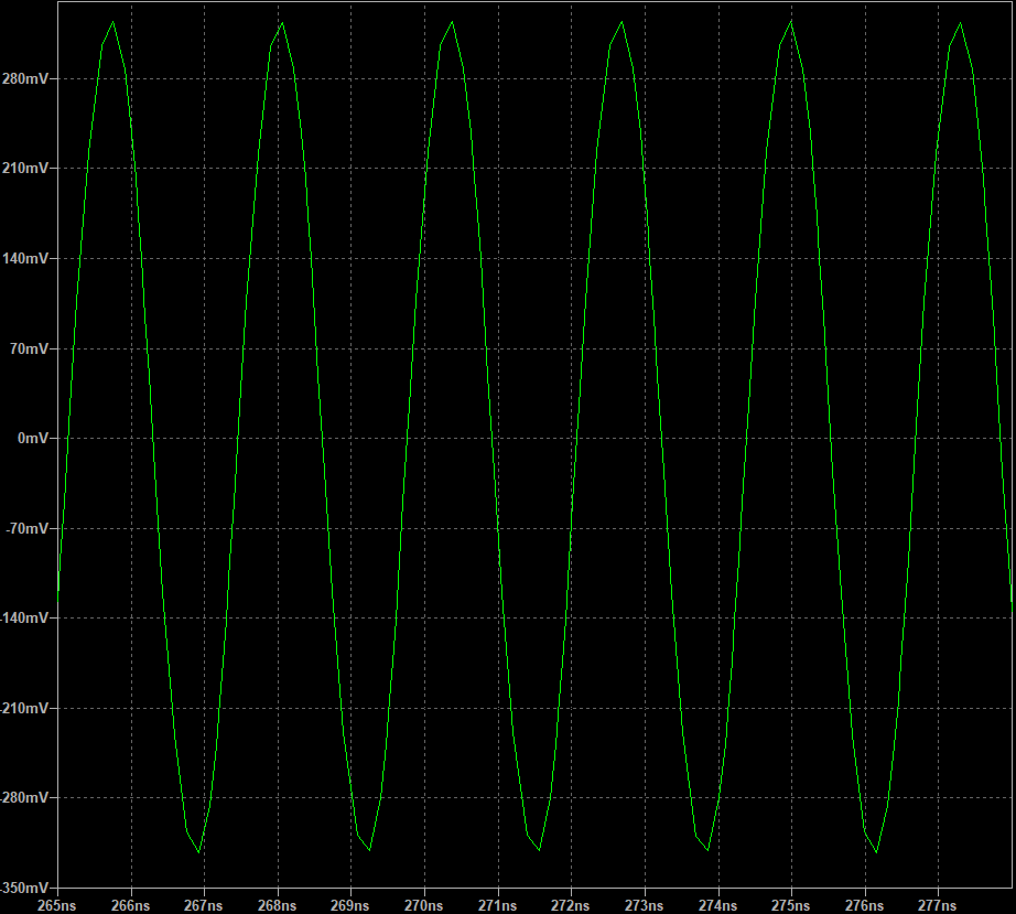
To make sure, I connected a 1.3GHz signal and than a 433MHz signal to it to see if it is working properly, and saw that I now have a very low amplitude coming from the 1.3GHz signal which was exactly what I have wanted:
Output when 1.3GHz signal is applied:
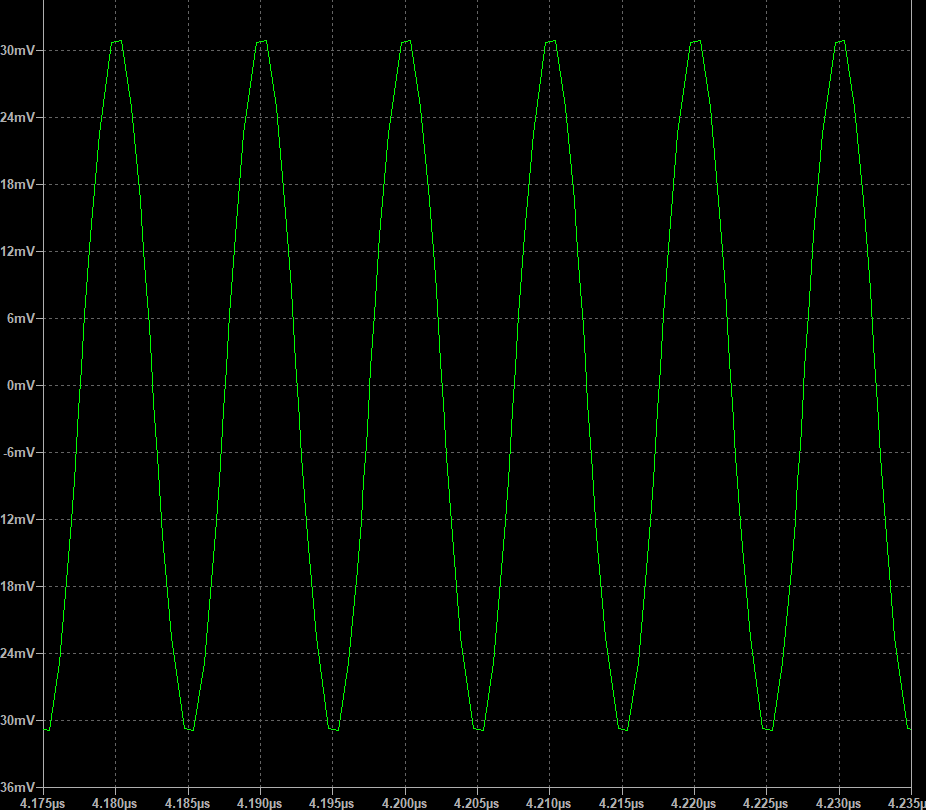
Output when 433MHzHz signal is applied: